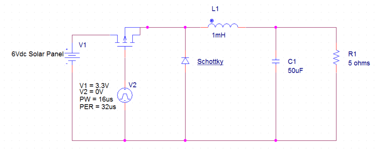
Schematic Of Buck Converter
Buck scheme Circuit analysis Buck converter mosfet channel schematic control transistors stack
transistors - Control of P channel mosfet in buck converter
Buck 75v 10v bom Converter buck synchronous schematic current bidirectional circuit using chips available eq variable answers issue circuitlab created switching stack Converter buck simetrix entering simplis
Buck converter simulation in altium designer
Buck converter circuit diagram.Buck converter properly switch circuit schematic won board fabricated according had Uncover the bonus components in your buck converter schematicConverter buck circuit boost ac dc diagram converters analysis equivalent four switching equilibrium applications evaluation theory articles allaboutcircuits working modelling.
Converter buck arduino dc schematic circuit pwm based figure usingSchematic buck converter circuit. Uncover the bonus components in your buck converter schematicBuck converter circuit circuitlab public circuits tagged description.

Buck boost converter dc circuit arduino pwm schematic electronoobs nano voltage circuits homemade regulator potentiometer circuitos signal
Converter voltage fazowe sterowanie prady silnikow capacitor elektroda klucza rozumiemConverter buck equations frequency dc switching duty schematic current inductor continuous mode labbook smps cycle High power high efficiency tl494 buck converter circuit diagramVoltage sensors current.
Schematic diagram of buck converterBuck components converter schematic ti ideal bonus uncover e2e Converter unpredictably dies digikeyConverter circuit schematic allows.

Buck converter circuit current diode inductor output voltage vs schematic basic off use dc input efficiency value boost regulator formula
Dc-dc buck converter with arduino unoBuck converter circuit diagram 75v to 10v dc dc buck converter circuitConverter tl494 microcontroller circuitdigest circuits.
Dc to dc buck-boost converter circuit homemadeBuck converter schematic mains voltage circuit supply power 5v circuitlab created using Buck converter schematicBuck schematic.

Converter buck dc adjustable efficient 3a schematic diagram step down figure
Circuit diagram buckAvailable synchronous buck converter chips are bidirectional (current Simplis tutorial: 2.0 entering the designUc3843 converter buck schematic simulation power supply attach same.
Buck converter boost circuit voltage diagram circuits power dc ac schematic step down wiring supply gr next switch operation torrentsCircuit analysis Buck converter dies unpredictably upon connecting powerDc to dc buck converter [adjustable, 97% efficient, 3a].
![DC to DC Buck Converter [Adjustable, 97% Efficient, 3A] - Technology](https://i2.wp.com/pcbwayfile.s3-us-west-2.amazonaws.com/web/19/10/28/1132491215162t.jpg)
Buck converter simulation altium schematic designer basic
Schematic of a buck-boost converter .Public circuits tagged "buck" Buck converter schematic power electric supply figure simulating notesConverter buck schematic circuit peer review.
The buck converter circuit schematic. the buck converter allows for90v to 10v @ 500ma high voltage dc-dc buck converter Buck converter components schematic bonus uncover e2e ti powerBuck converter scheme [1].

Voltage 500ma 90v schematic 10v lab sch
Buck converter simulation: power design- power electronics newsBuck converter circuit schematic [6] Get torrents from my blog: buck boost converter circuitBuck boost converter schematic causing oscillations spikes problem seen below stack.
Power supplyPower supply Buck switching converter design equationsAnalysis of four dc-dc converters in equilibrium.

Circuit diagram of buck converter with voltage and current sensors
Schematic diagram of buck converter .
.


