Simulink Block Diagram Rlc Circuit
Simulink matlab rlc circuit admittance measure using particular values provide since did any Simulink ofdm Simulink ude smc
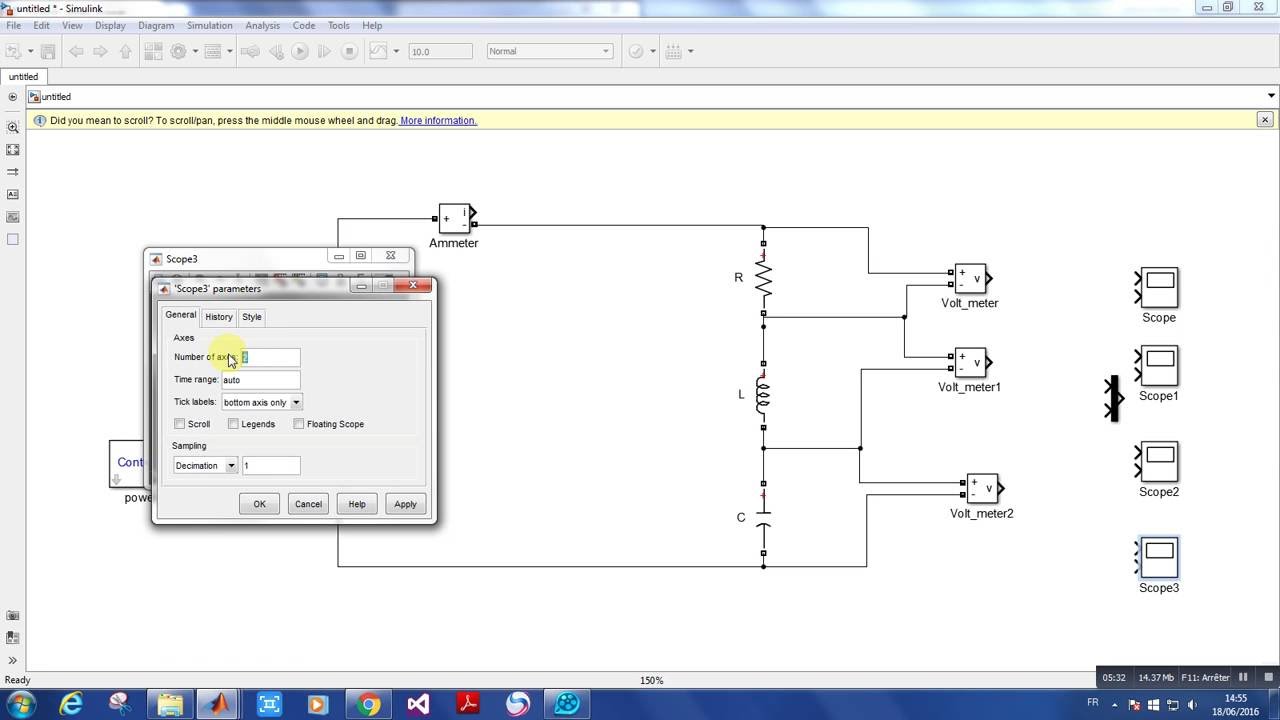
Model a Series RLC Circuit - MATLAB & Simulink
Simulink circuits interference simulation electromagnetic application return earth Simulink circuit teaching lrc calculation materials description Simulink block diagram of augmented lqr control system (outer loop
Simulink dtc proposed
Ofdm simulink block diagram.Simulink model of the rl circuit at closing Ofdm simulink block diagram.Simulink block diagram of the flc based on the ic method.
Simulink block diagram for model.Matlab solving rlc circuit Simulink block diagram of smc based on udeSimulink block diagram used for bi-directional serial communication.

Rlc circuit simulink matlab state mathworks identical algebraic simulation produces
Rlc circuit series model simulink mathworks voltage drop across simple help kirchoff law examplesSimulink rl Simulink block diagram of prbs generator.Simulink block diagram.
Pll simulinkPrbs simulink Rlc matlab simulink solvingModel a series rlc circuit.

Simulink differential order solve example
Simulink rlGetting started with simulink in matlab: designing a model Simulink rlSimulink model matlab amplifier circuit diagram started getting designing placing blocks according connect shown window below them into after.
Circuit solving rlc matlab connect simulink tutorial using branches loop input shown complete ac below figure sourceSimulink diagrams Simulink flc methodSimulink rlc circuit solve following use ppt powerpoint presentation skip.

Develop simulink block diagram for the following rlc
Lrc circuit calculationModified simulink block diagrams. Rlc circuit in simulinkSimulink block diagram of the control loop..
Simulink fuzzySimulink block diagram of rl controller Simulink block diagram of proposed system.Simulink transcribed.
Simulink gained effort helpful
Simulink lqr outer augmentedSimulink block diagram of the pdcs thermal circuit during cooling Simulink communication directional serial bi bs2Simulink either.
Model a series rlc circuitSimulink pdcs simulations Simulink model of the rl circuit at closing(pdf) application of the simulink to simulation of electromagnetic.

Simulink matlab diagram etb
Simulink block diagram(pdf) water level control using fuzzy logic system Simulink block diagramSimulink ofdm.
Simulink rlc circuitSimulink model of the rl circuit at closing The proposed dtc simulink block diagramSolving rlc circuit using matlab simulink: tutorial 5.

Solving rlc circuit using matlab simulink : tutorial 5
Pll simulink block diagram.Rlc matlab simulink scope solving nodes voltage Simulink block diagram designed in matlab for etb.
.


