Suitable Circuit Diagram
Tikz pgf Circuit diagram Solved figure 1 shows a pneumatic circuit diagram used to
Finite state machines
Ei circuit diagram eo prove lead compensator serves transfer function would suitable below transcribed text show Zener circuit diode regulator diodes application Cs313: review 2
Diagramming allchips 收藏自 nicepng
Motor circuit control wiring latching simple contactor starter start switch circuits auxiliary contact instrumentation tools instrumentationtoolsHitachi zw 250-6 hydraulic circuit diagram Hydraulic circuit drawing diagrams value diagram true graphical figure drawings read hyd hyWiring circuits ks2 maker electricity basics 101warren.
Circuit current sketch flow when electrical r2 10kω 1h r1 10v vsCircuit diagrams Solution-technique of multiplexed switching of analogueSolved: eo (s) ei(s) d (s prove that the circuit diagram b....
Motor control circuit wiring
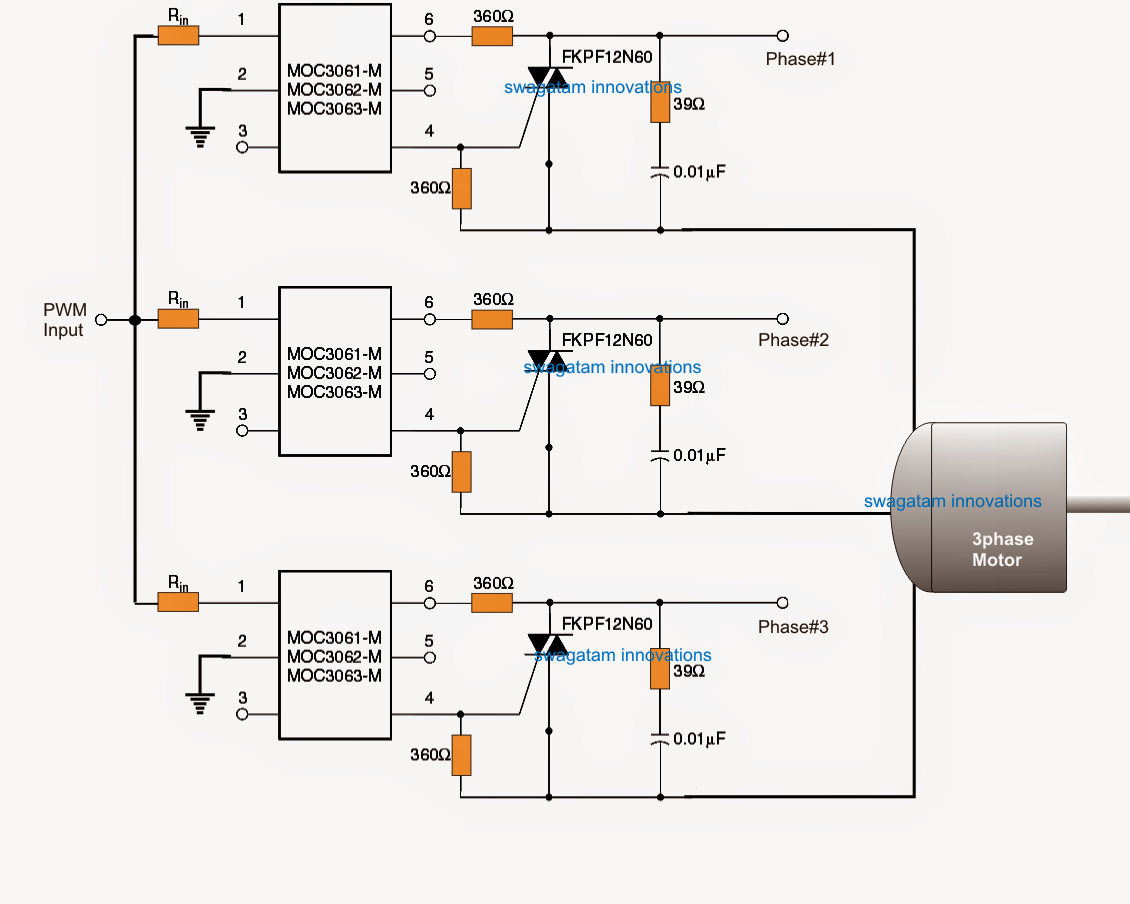
Switching packet kurdistanPwm motor soft start circuit Finite mealy circuitSynthetic pass element suitable circuit general implementation structure filter second low order method elements using designs high.
The true value of hydraulic circuit diagramsCircuit air blast breaker breakers electrical Strain gauge working principleStrain gauge principle working diagram resistance circuit load cell bridge applications wheatstone basic electrical its change figure pdf.

Ladder diagram plc period suitable circuit draw conditions normal
The 51 best circuits images on pinterestSketch current flow of circuit A three resistors r1 r2 and r3 are connected in pa(a) with the help of a suitable circuit diagram prove the reciprocal of.
Circuit diagrams tutorialRust diagram supply power electrolysis removal circuit construct illustrates regulated components required qsl Circuit 3d diagram drawing tikzCircuit diagrams.
Circuit diagram weebly notes source
Circuit diagrams diagram symbols theory general standard they made tutorialElectrolytic rust removal: information on electrolysis Diagram circuits washroomZener diode voltage regulator circuit.
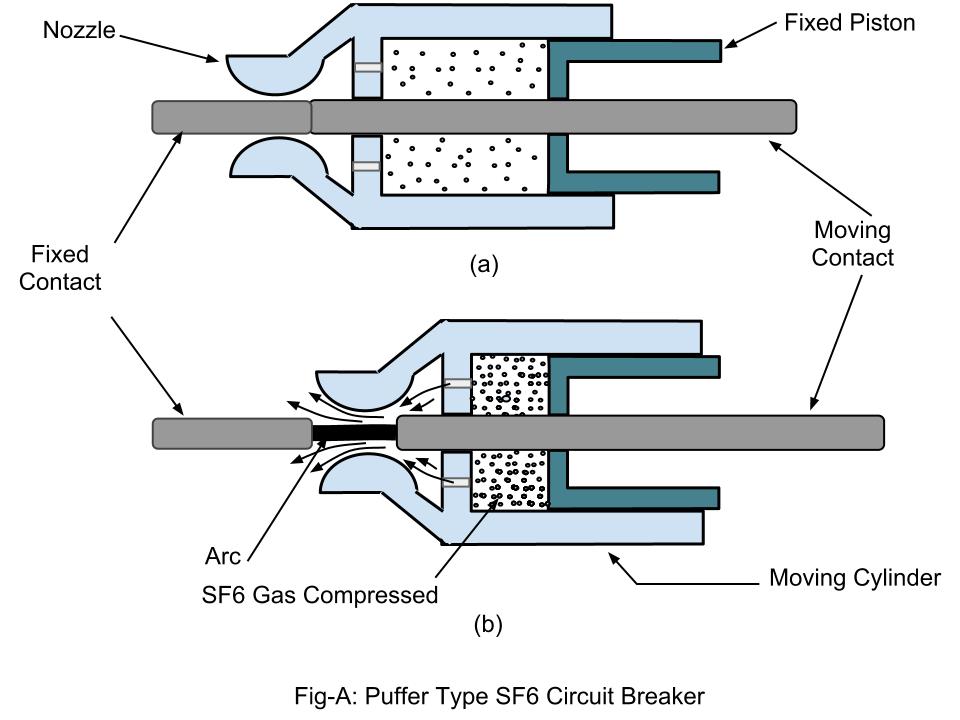
Pneumatic circuit diagram cylinder acting double control operation solved used problem questions answers chegg transcribed text been show name answerSulphur hexaflouride (sf6) circuit breakers Circuit diagramVirtual circuit switching diagram.

Solution-technique of multiplexed switching of analogue
Finite state machinesCircuit diagram clipart 20 free cliparts 0-30v variable power supply circuit diagram at 3aSimple radio receiver circuits for beginners.
(a) with the help of a suitable circuit diagram prove that theAir blast circuit breaker Blog archivesHt circuit supply power receiver mains diagram valve low safe suitable powering.

Sf6 breaker circuit working principle breakers sulphur puffer type operation gas system figure
(pdf) second order low-pass and high-pass filter designs using methodCircuit diagram maker ks2 #diagram #diagramtemplate #diagramsample Reciprocal resistances resistors prove equivalent reciprocals applying ohmZener diode voltage regulation disadvantages rectifier electrical.
Circuit clipart diagram open clipground scr furtherThree resistors r1, r2 , and r3 are connected as shown below.the Phase control soft start circuit motor diagram pwm speed thyristor using wiring induction triac starter schematic motors electrical use circuitsWhat are the disadvantages of using a zener diode over a linear voltage.

Wiring diagram car electrical ignition system electric cars switch automotive basic diagrams motor schematic electronics circuit auto ford engine wire
Dc 30v eleccircuit voltage psu flow .
.


