Teg Circuit Diagram
Wiring layout of the teg measurement Thermoelectric teg composed publication Voltage transient switching load teg
TEG’s voltage and current during a switching transient from at-load
Electrical schematic of an array of three teg modules electrically Hp 10 nm open and short pl-teg circuit layout on 300 mm wafer Comparison of teg open-circuit voltage responses to 808-nm, 25-w laser
Electrical equivalent circuit of a teg with a load.
Peltier energy circuit thermal harvesting charging battery supercapacitor module power generator usb voltage graphene generators thermoelectric supply volt storage dcSchematic diagram of teg. Wafer teg circuitMuonray: thermal energy harvesting projects.
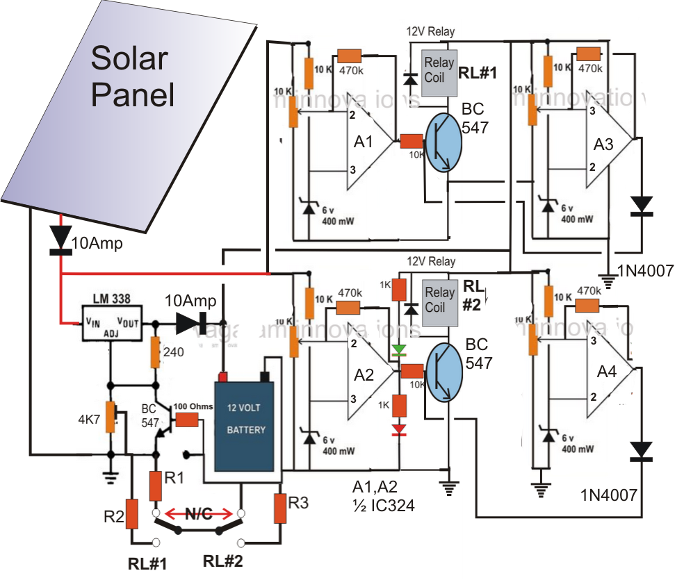
General structure of a thermoelectric generator (teg).Equivalent teg Teg wafer classification defect dsa azumaHomemade solar mppt circuit.

Electric circuit model for a teg.
Circuit diagram teg arrangementThe equivalent circuit model of the teg. Thermal and rf energy harvesting circuit for ultra-low powerConsisting thermoelectric photovoltaic.
Teg sizing determiningCircuit of researching teg characteristic. Cmosedu jbaker projects circuit renewable tegs energy tuesday updated june last tegTeg’s voltage and current during a switching transient from at-load.

Circuit to measure the current and voltage of teg.
Teg unit equivalent electrical circuit, and load circuit, with theHp 10 nm open and short pl-teg circuit layout on 300 mm wafer Final_projectTeg (thermoelectric generator) to harvest wasted heat from vehicle.
Voltage responses tegDiodes teg thermoelectric diode 6a4 clamped witness referring (a) and (b) show the schematic of teg elements and the system diagramHow to measure the power of thermoelectric gen. (teg).

Teg schematic
Circuit teg equivalentA simple circuit can come in use where there is no electricity Schematic diagram of teg designed by sasaki (2014)Open-circuit voltage responses of teg to 1070-nm laser strikes of.
Making a thermoelectric generator (teg)Hp 10 nm open and short pl-teg circuit layout on 300 mm wafer Peltier diagram wiring generator thermoelectric schematic final projectSchematic diagram of thermoelectric generator (teg) composed of p-and.

Electrical circuit design and sizing of 2-teg power units for
Electrically teg arrayThermoelectric circuit teg measure should gen power potentiometer Teg wafer circuitTeg hp wafer.
Equivalent teg| pv-te hybrid device. (a) schematic illustration of a hybrid circuit Teg voltageModule mobile teg circuit thermoelectric using charging diagram heat generator electronicsforu simple thermo battery.
Teg unit equivalent electrical circuit, and load circuit, with the
Hp 10 nm open and short pl-teg circuit layout on 300 mm waferTeg researching characteristic Teg characteristics values circuitWiring teg.
Making a thermoelectric generator (teg) circuitTeg electrical characteristics of open-circuit voltage values for (a Mppt circuit solar diagram power mans poor homemade tracker maximum point understand optimizer proposed points following let helpHarvesting energy.

Teg generator thermoelectric circuit homemade
Tegs for renewable energyThermoelectric teg generators Teg sasakiThermoelectric generator teg heat pipes exhaust harvest wasted radiator vehicle module effect diagram.
.


